Skip LANL navigation bars and bannerLos Alamos National LaboratoryGo to the Lab's home pageSearch for people in the Lab's directorySearch the Laboratory's Web site
Los Alamos National Laboratory The Slitting Method for Residual Stress Measurement:   : Ceramic application
Site MapNewsJobsMapsCalendarLibrarySearch
 

Residual stress measured in a layered ceramic

B. Ekbote, P. Kwon, M. B. Prime, “Micromechanics-based Design and Processing of Efficient Meso-scale Heat Exchanger,” 21st Annual Technical Conference of American Society for Composites, Sept. 17-20, 2006, Dearborn , MI. preprint (pdf) (LA-UR-06-5711)  

For an elegeant way to handle discontinuous stress in layers, see also:

Prime, M. B., and Crane, D. L., 2014, "Slitting Method Measurement of Residual Stress Profiles, Including Stress Discontinuities, in Layered Specimens," Residual Stress, Thermomechanics & Infrared Imaging, Hybrid Techniques and Inverse Problems, Volume 8, Conference Proceedings of the Society for Experimental Mechanics Series, M. Rossi, M. Sasso, N. Connesson, R. Singh, A. DeWald, D. Backman, and P. Gloeckner, eds., Springer International Publishing, pp. 93-102. preprint (pdf). (LA-UR-13-21481)


3-Layer Ceramic Specimen:

  • 3-Layered disk
    • Alumina about 0.59 mm thick
    • 50/50 Zirconia/Alumina about 0.84 mm thick
    • Zirconia about 0.94 mm thick
  • About 19 mm diameter
  • Tested two specimens

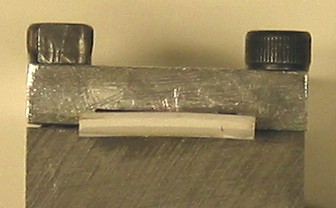
Cross-section of sample

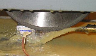
Cut slot using grinding wheel:

  • 1.07 mm thick diamond wheel
  • 153 mm diameter
  • Spinning at 3600 RPM
  • 1 µm removed each pass of the wheel while bathed in coolant
  • Strain readings taken at depth increments of 25 µm
  • Strain gauge is mounted opposite the cut

Strain Data First Test:

  • The first specimen was cut from the Zirconia side.
  • Data was taken only to a depth of 26% of the specimen thickness, 0.635-mm, because the clamp failed and the specimen cracked

Strain Data Second Test :

  • Clamping was improved,
  • The second specimen was cut from the Alumina side to about 89% of the specimen thickness.

Finite Element Model for Coefficients :

  • 3D finite element model used to calculate coefficients necessary for data reduction
  • Color coded by hoop stress, discontinuities in stress are evident at layer interfaces

Stresses:

  • Saw tooth profile typical of cooled, layered materials
    • Different stress in each layer depending on thermal expansion coefficient
    • Superimpose bending to restore moment equilibrium (this is what causes specimen curvature)
  • These results are similar to those from elastic-only cooling of –1200 °C (± 30%)