| |
Residual Stress
Conferences |
  |
|
|
|
 Measure
Surface
Measure
Surface |
|
**** You
can also measure the surface using laser scanning. See this paper:
 M. B. Prime, R. J. Sebring, J. M. Edwards, D. J. Hughes,
P. J. Webster, "Laser Surface-Contouring and Spline Data-Smoothing
for Residual Stress Measurement," Experimental Mechanics,
44(2), pp. 176-184, April 2004.(LA-UR-02-7241)
M. B. Prime, R. J. Sebring, J. M. Edwards, D. J. Hughes,
P. J. Webster, "Laser Surface-Contouring and Spline Data-Smoothing
for Residual Stress Measurement," Experimental Mechanics,
44(2), pp. 176-184, April 2004.(LA-UR-02-7241)
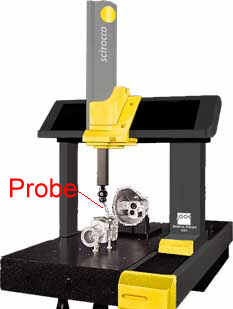
Probably the simplest and most
widely available way to measure the contour of the newly cut surface is
to use a Coordinate Measuring Machine or CMM
|
|
A CMM positions a touch
trigger probe using a precision 2-axis (x,y) control system.
CMM's come in sizes ranging
from desktop size to big enough to measure cars.
Picture: Brown
and Sharpe
|
|
|
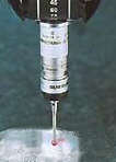
Then the touch trigger
probe registers contact with the surface. The location of the probe
tip is combined with the machine coordinates to give a 3-D position
of the surface.
Common tips include ruby
spheres of 1-10 mm in diameter.
|
- CMM's can automatically
scan a surface and measure thousands of data points quickly.
- A few micron precision is
readily achievable
- CMM's are widely available
in inspection labs and machine shops at Universities and private shop
|
|