Los Alamos National LaboratoryGo to the Lab's home pageSearch for people in the Lab's phone book
     
  logo

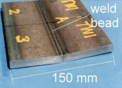
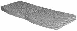
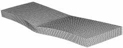
Applications: Residual Stress Map in Weld Plate

 
transparent spacer
 
HOME
Principle
   - make cut
   - measure surface
   - calculate stress
Validations
Applications
   - bent beam
>    - weld plate
   - quenched steel
   - impacted plate
   - alum. forging
   - friction stir weld
   - Ti FSW
   - Railroad rails
Publications
More info
 
Residual Stress
Conferences
Vertical Linetransparent spacer

download paper paper on these measurements: M. B. Prime, R. J. Sebring, J. M. Edwards, D. J. Hughes, P. J. Webster, "Laser Surface-Contouring and Spline Data-Smoothing for Residual Stress Measurement," Experimental Mechanics, 44(2), pp. 176-184, April 2004. (LA-UR-02-7241)

Results: Axial Residual Stress Map Measured Over Plate Cross-section:

  • Great results!
  • Agreement between contour and neutron results is better than combined uncertainty.
  • Neutron mapping done at Chalk River Labs in Canada by Dr. Darren Hughes and Professor Peter Webster of Engineering Science Group at the University of Salford, UK
  • Specimen prepared by TWI as part of VAMAS-TWA 20 effort to standardize neutron diffraction measurements of residual stress
  • Some report of variability of neutron results in this specimen available in D.J. Hughes, P.J. Webster and G. Mills, Mater. Sci. Forum 404–407 (2002), pp. 561–566 pdf from publisher. However, that is only strains, not stresses.
Details of this measurement and specimen:
Weld Plate
  • Ferritic steel: BS 4360 50D
  • 12.5 mm thick (1/2 inch)
  • 6 mm wide, 8 mm deep groove machined along length
  • Filled in with 12 pass TIG weld
specimen photo
Weld Plate

Cut Beam using wire EDM
  • Beam carefully clamped during cutting. See picture.
  • Use 100 µm (0.004") diameter wire.
  • Cut using "skim cut settings" so that minimal stresses are put in during cutting.
how plate was clamped during cut
Sketch of EDM Cut

Measure Surface Contour with CMM
  • Use 4 mm diameter ruby tip on CMM
  • Measure surface (both halves) on a 0.4 mm grid: gives ~12,000 data points
  • Peak-to-peak contour of about 75 µm (0.003")
deformed shape
Shape of cut surface, magnified 80x

Calculate Stress using FEM
  • Make 3-D model of weld plate after cut
  • Start with flat surface
  • Using displacement boundary conditions, force cut surface to opposite of measured contour
  • Extract stresses normal to surface.
deformed FEM
FEM model forced to opposite shape of contour, magnified 80x


transparent spacer       transparent spacer
   

Managed by Triad National Security, LLC Los Alamos National Security, LLC for the U.S. Department of Energy's NNSA
contact: Mike Prime at prime@lanl.gov | Copyright & Disclaimer
U.S. patent 6,470,756 | Last Modified: October 26, 2012

spacer spacer spacer spacer