| |
Residual Stress
Conferences |
  |
 paper on these measurements and FEM model
Results:
- Shows stress maps
on two cross sections of same forging, shown in blue and red in sketch
- Periodic stress variations
from cold compression process described below
- Because of large size of
part and intricate spatial variations of stress, probably no other technique
could have measured this
- These forgings are critical
aerospace components, and residual stresses cause distortion problems
in manufacture
- Dashed lines are
zero stress contours
Highlights
of this measurement and specimen:
Specimen
and EDM cutting:
- 7050 Aluminum
alloy hand forging
- Original
dimensions: 107 mm X 155 mm X 710 mm (4.2" X 6.1" X
28")
- Solution
heat treated and quenched into Alcoa Proprietary Quench
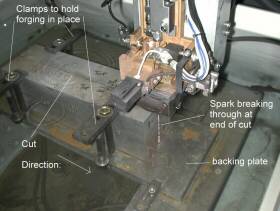
- Picture
shows one piece of forging being cut by wire
EDM. This cut is the one shaded in blue
in the graphic at the top of the page. The forging had already
been cut in half lengthwise.
- Cuts were
made using 150 µm brass wire and "skim cut" settings
|
 |
Quenching
Stresses :
- 7050-T74
Aluminum forging
- This is
BEFORE cold compression stress relief
- Dimensions:
107 mm X 155 mm X 710 mm (4.2" X 6.1" X 28")
- Solution
heat treated and quenched into Alcoa Proprietary Quench
- This is
from cutting forging in half lengthwise before red and blue cuts
in graphic at the top of the page.
|
|
Stress
Relief :
- A second
forging was stress relieved by overlapping cold compression
- Now the
material is 7050-T7452 Aluminum
- This is
attempt at relieving stress by uniform plastic deformation. For
plate this is done by stretching and is very effective, see measurements
of stress relief in plate.
|
|
Measure
contour :
- After EDM
cut shown in picture farther up on page, measure surface contour
- Measured
using CMM, 1 mm diameter ruby tip
- Measured
on 2 mm grid, giving about 14,000 points
- Peak-to-valley
is about 60 µm, easy to measure
- This is
for cut shaded in blue in the graphic
at the top of this page
|
 |
FEM
stress calculation:
- To calculate
stress, elastically forced FEM model into opposite of measured
contour (shown just above this)
- Displacements
exaggerated to show shape
- This shows
calculation for cut shaded in blue
in the graphic at the top of this page
- The background
image on the home page is the FEM model
for the other cut, the red one in
the graphic at the top of this page
|
 |
|
|