Los Alamos National LaboratoryGo to the Lab's home pageSearch for people in the Lab's phone bookSearch the Laboratory's Web site
     
  logo

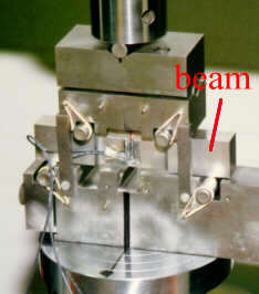
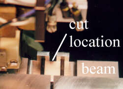
Applications: Bent Beam

 
transparent spacer
 
HOME
Principle
   - make cut
   - measure surface
   - calculate stress
Applications
>    - bent beam
   - weld plate
   - quenched steel
   - impacted plate
   - alum. forging
   - friction stir weld
   - Ti FSW
Publications
More info
 
Residual Stress
Conferences
Vertical Linetransparent spacer
Stress Map Measured Over Beam Cross-Section:
predicted stress map
Bend Test Prediction
measured stress map
Measurement Results
scale
Plot Scale

through-thickness stress plot

Results also plotted as through-thickness curve. Agreement with prediction is very good!
Details of this measurement and specimen:
Steel Beam
  • Austenitic stainless steel
  • 10 mm X 30 mm cross section
Bend to put in known residual stress
  • Bend in 4-point bending fixture.
  • Measure strain on top and bottom of beam during loading and unloading.
  • Calculate residual stress from strains and loads.
beam beding photo

Cut Beam using wire EDM
  • Beam carefully clamped during cutting.
  • Use 100 µm (0.004") diameter wire.
  • Cut using "skim cut settings" so that minimal stresses are put in during cutting.
EDM cutting photo

Measure Surface Contour with CMM
  • Use 4 mm diameter ruby tip
  • Measure 10 x 30 mm surface with a 50 x 300 grid of points.
Photo of CMM tip

Calculate Stress using FEM
  • Make 3-D model of beam after cut.
  • Apply opposite of measured contour as displacement boundary conditions.
  • Extract stresses normal to surface.
FEM mesh


transparent spacer       transparent spacer
   

Operated by the University of California for the US Department of Energy
contact: Mike Prime at prime@lanl.gov | Copyright © UC | Disclaimer
U.S. patent 6,470,756 | Last Modified: March 12, 2007

spacer spacer spacer spacer