DOE/LANL Jurisdiction Fire Danger Rating:
  1. LANL Home
  2. engage
  3. collaboration
  4. feynman center
  5. tech and capability search
  6. acoustic camera

Acoustic Camera

Turning opaque fluids into working environments

technology Snapshot

Overview

When water turns murky or dense with mud, sediment or chemistry, optical cameras stop being useful, and operators are left guessing about what lies on the other side of the fluid. The Acoustic Camera from Los Alamos National Laboratory replaces that guesswork with sharp 3D imagery generated from sound, achieving sub-millimeter depth resolution in near real time. Instead of inferring the size and orientation of a submerged object from an impression block or a low-frequency sonar return, an operator receives an actual shape, with depth cues and material hints, on the first pass. The result is faster decisions in environments that have historically been opaque, whether the goal is recovering a lost tool from a wellbore, checking the integrity of a net pen in a turbid fjord, or inspecting submerged infrastructure where flushing or cleaning the surrounding fluid is not an option.

How it Works:

The system operates by transmitting high-frequency ultrasonic pulses—typically in the hundreds of kilohertz range (approximately 100–800 kHz)—into the wellbore toward an object of interest. These sound waves reflect off the object and are captured by a two-dimensional acoustic receiver array. By measuring the time-of-flight and spatial distribution of the returned echoes, onboard digital signal processing reconstructs a detailed 3D image of the object in near real time. Because ultrasound propagates through drilling mud and other optically opaque fluids, the system can generate clear 3D images without requiring fluid replacement or well cleanout.
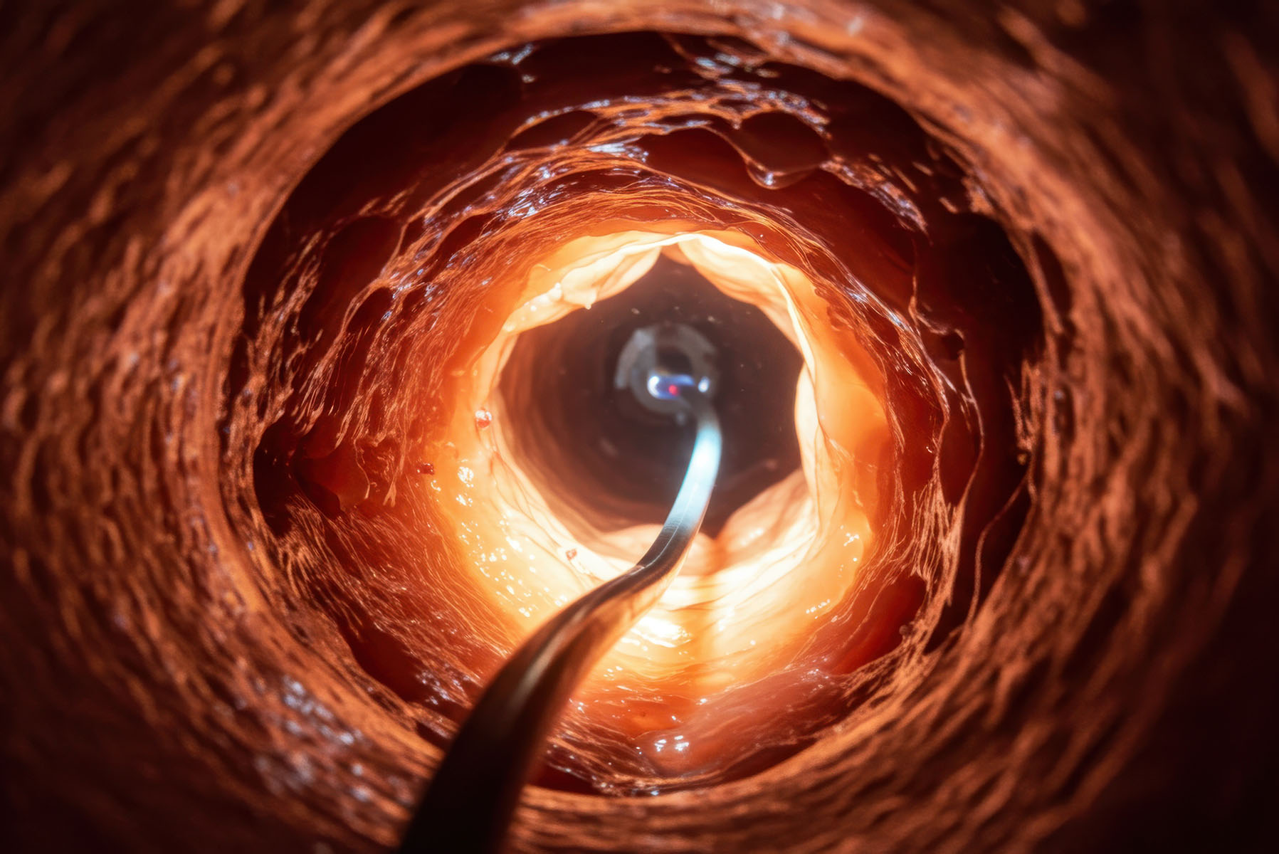
Adobe Stock image used for illustration purposes only

Advantages

  • Imaging through opaque fluids: Enables 3D visualization in drilling mud and other optically opaque, acoustically attenuating fluids where optical systems fail 
  • Reduced cost and downtime: Eliminates the need for well cleanout and accelerates diagnostic decision-making during fishing operations 
  • Higher-quality diagnostics: Provides accurate 3D information on object shape and orientation, surpassing mechanical impression methods
  • Lower operational risk: Improves fishing-tool selection and reduces the likelihood of failed recovery attempts or well loss 
  • Extensible platform: Applicable to other downhole and industrial environments involving optically opaque fluids, supporting future product expansion 

Technology Description

Acoustic Camera uses a broadband piezoelectric transducer to insonify the object with frequencies between roughly 100 kHz and 800 kHz. Because attenuation in fluids scales with the square of frequency, this band is chosen as the practical compromise between mud penetration (favoring lower frequencies) and image resolution (favoring higher frequencies). Reflected pulses pass through a compound high-density polyethylene (HDPE) acoustic lens consisting of a fixed plano-concave primary element and a motor-positioned secondary element, allowing focus adjustment without changing the receiver position, and yielding an appropriate magnification factor.

The receive array is a 2D segmented piezoelectric detector submerged in sound-communicating fluid whose low sound speed provides a roughly three-fold reduction in wavelength versus water and enables a compact camera housing. Image reconstruction can use either tone-burst excitation with first-arrival extraction or, for higher resolution, frequency-chirp excitation followed by cross-correlation of the transmit and receive signals — yielding depth resolution below 1 mm at working distances of up to approximately 2 feet in drilling mud. The film allows the source and detector to share a single optical axis, eliminating the multiple reflections and aberrations introduced by semi-transparent acoustic mirrors used in earlier architectures.

Market Applications

  • Oil and Gas
  • Mining and Geotechnical Operations
  • Enhanced Geothermal Systems
  • Industrial Inspection and Maintenance
  • Energy and Utilities Infrastructure
  • Government and Defense 

On This Page

Overview

Advantages

Technology Description

Market Applications

Published: 2026-07-07

LA-UR-26-24351

Application Area

Sectors:Advanced Materials & Manufacturing

Areas:Advanced Manufacturing, Operations Management, Sensing

Industries:Devices and Instruments, Environmental Remediation, Mining, Oil and Gas, Water

Markets:Condition Monitoring, Operations Management

Technology Readiness Level:

4 - Component Prototypes Tested in a Controlled Environment

IP Information

Patent Number: U.S. Patent No. 10,054,676-B2

S Number: S-129409.002

Contact

  • Licensing
  • Los Alamos National Laboratory
  • licensing@lanl.gov
Download PDF

Connect With Our Innovators

Get Connected

Access Our Technical Expertise

Our Expertise

Explore Ways to Partner With Us

Ways to Partner

Los Alamos National Laboratory

P.O. Box 1663

Los Alamos, NM 87545

(505) 667-5061

At The Lab

  • Business Opportunities
  • Jobs
  • Organizations
  • Research Library
  • User Facilities

Information

  • Emergency
  • Ombuds
  • Reading Room
  • Resources
  • Science Museum

For Employees

  • AskIT
  • LANLInside
  • MyMail
  • Training
DOE White Seal
  • Terms of Use/Privacy

Managed by Triad National Security, LLC for the U.S. Dept. of Energy’s NNSA

Copyright 2026 Triad National Security, LLC. All Rights Reserved.

Learn about the Department of Energy’s Vulnerability Disclosure Program