| |
Residual Stress
Conferences |
  |
|
|
|
|
 Calculate
Stress
 |
For help with calculations:  (26 MB) Johnson, G, 2008, "Residual stress measurements using the
contour method," Ph.D. Dissertation, University of Manchester, School of Materials. A very thorough thesis with lots of practical and helpful information on the contour method and then some very good applications including several advances.The Matlab files described in the dissertation and some examples are available here: GJohnsonFiles.zip (3.6Mb). Use of the spline program requires the curve fitting toolbox. (Posted with permission of author) (26 MB) Johnson, G, 2008, "Residual stress measurements using the
contour method," Ph.D. Dissertation, University of Manchester, School of Materials. A very thorough thesis with lots of practical and helpful information on the contour method and then some very good applications including several advances.The Matlab files described in the dissertation and some examples are available here: GJohnsonFiles.zip (3.6Mb). Use of the spline program requires the curve fitting toolbox. (Posted with permission of author)
Build finite element
model of cut part
- No need
to model actual deformed shape - displacements are small
- Shown here
in 2-D, build 3-D model to get full cross-sectional stress map
|
|
Take opposite
of measured contour
- Because
we need to force deformed shape back to flat
|
|
Apply to finite element
model
- Apply to
edge of model as displacement boundary conditions
- Apply in
normal direction only, leave other directions unconstrained
|
|
Extract results
- Post-process
finite element results to get stress along edge where boundary
conditions were applied
|
|

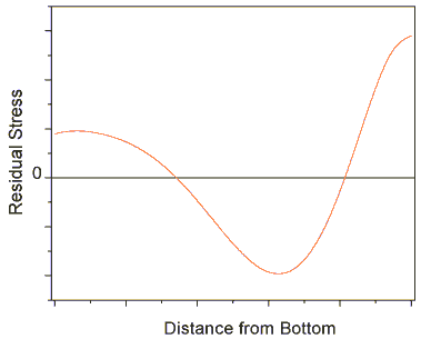
Now we have the residual stresses
that originally existed normal to the plane of the cut! Illustrated here
for just a 1-D stress profile, but see Applications
for examples of getting a full 2-D stress map.
|
|
